FAN DISC
  • Home
  • Spring Selection
    • Precision Belleville Springs >
      • .236 to .394
      • .472 to .492
      • .551 to .591
      • .630 to .709
      • .787 to .886
      • .906 to .984
      • 1.100
      • 1.240 to 1.340
      • 1.400 to 1.770
      • 1.970
      • 2.200 to 2.360
      • 2.480 to 2.800
      • 3.150 to 3.540
      • 3.940 to 4.410
      • 4.920
      • 5.510 to 7.090
      • 7.870
      • 8.860 to 9.840
    • AI Springs >
      • AI .187 to .950
      • AI 1.000 to 1.750
      • AI 2.000 to 2.500
    • SP Belleville Springs >
      • SP .197 to .945
      • SP 1.142 to 3.031
    • CONTACT Disc Springs >
      • CONTACT Narrow
      • CONTACT Regular
      • CONTACT Wide
    • K Disc Springs >
      • Metric for K
      • Inch for K
    • FL Disc Springs >
      • Metric for FL
      • Inch for FL
  • Special Springs
  • Spring Design
    • Tolerances >
      • for Thickness
      • Overall Height
      • Hardness Range
      • OD + ID Guide Clearance
      • OD + ID Tolerance
      • Load Tolerance
    • Load Calculations >
      • Nomenclature
      • Load in Lbs
      • True Radius Factor
      • Corner Radius Factor
      • True Cone Height Factor
      • Flattening at Edge Factor
      • Precise Load Computing
    • About >
      • Contact Us
      • News Releases >
        • Fan Disc Second Patent
        • JPL Selects Fan Disc
        • Fan Disc Wins Patent
    • Load and Stress Calculations
    • Dynamic Loading
    • Materials Properties
    • Tightening Torque Values
    • Typical Disc Spring Apps
  • Site Map

fl seriES DISC springs 

Request a Quote

Inch Disc Springs for Flange Applications

FL SERIES DISC SPRINGS INDEX
Spring Discs
Springs Discs
Metric Spring Discs
Inch Spring Discs
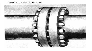
Spring Discs are an elastic mechanical element. When used in bolt joints that are subject to thermal or mechanical shock, they deflect and move with the bolted joint. Hence, they compensate for developed looseness. The reactive power of the spring disc serves to keep the bolt joint tight under all conditions. Principal applications include piping construction, compression joints, steam piping joints, valve and pump connections, and others in the petrochemical field.

A principal cause of flange leakage is abnormally high loads produced by thermal expansion and contraction of a bolted joint. Generally, flanges are under static load conditions. However, in large piping systems, there may also be mechanical shock from compressor related piping. Thermal and mechanical shock differential can cause variation and yielding in bolt loads. To protect against these conditions, always use spring discs under the nut or bolthead.

Pre-stressing or torquing the bolt at factory installation is not sufficient to protect the flange joint under unexpected temperature variations and mechanical shock loads in the field. By absorbing peak stresses, spring discs prevent damage to the bolt, gasket and joint.

Part Numbers include FL-388, FL-716, FL-889, FL-10125, FL-12131, FL-14160, FL-16168, FL-18187, FL-20190, FL-22250, FL24250, FL-26262, FL-28281, FL-30300, FL-32318, FL-36356, FL-40394
Picture
Click to enlarge
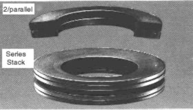
*For single spring disc; for higher loads, use parallel stacks. Note: Load calculated for 17/7 PH stainless steel with large radii, R=t/4
Material: STAINLESS: 17/7 PH (Armco) precipitation hardened Hardness: Rc-38-43 TEMPERATURE RANGE: -220 C to +300 C For higher temperatures, to +600 C we can supply Inconel X-750 (non standard) Note: For normal operating temperatures, we can supply Chrome Vanadium SAI 6150.

Tolerance: OD - Plus .000/Minus 1.5% x OD (designed for standard Flange spot face diameter) (D-Minus .000/Plus/Minus 1.5% ID THICKNESS - Plus/Minus 5% x normal thickness shown LOAD - Plus/Minus 20% of nominal shown (when ordering, ALWAYS specify materials after part number)

Picture
Typical Application
Picture
Stack and Cross-Section

Home | Spring Selection | Special Springs | Spring DESIGN | About | Request Quote

FAN DISC CORPORATION
​8127 Clybourn Avenue
Sun Valley CA 91352
Tel (818) 767-1886
Fax (818) 767-7415
​www.fandisc.com
[email protected]
Picture
​ISO 9001:2015 Certified
Copyright ©2020-2023 Fan Disc Corporation • Privacy Policy • Site Map
  • Home
  • Spring Selection
    • Precision Belleville Springs >
      • .236 to .394
      • .472 to .492
      • .551 to .591
      • .630 to .709
      • .787 to .886
      • .906 to .984
      • 1.100
      • 1.240 to 1.340
      • 1.400 to 1.770
      • 1.970
      • 2.200 to 2.360
      • 2.480 to 2.800
      • 3.150 to 3.540
      • 3.940 to 4.410
      • 4.920
      • 5.510 to 7.090
      • 7.870
      • 8.860 to 9.840
    • AI Springs >
      • AI .187 to .950
      • AI 1.000 to 1.750
      • AI 2.000 to 2.500
    • SP Belleville Springs >
      • SP .197 to .945
      • SP 1.142 to 3.031
    • CONTACT Disc Springs >
      • CONTACT Narrow
      • CONTACT Regular
      • CONTACT Wide
    • K Disc Springs >
      • Metric for K
      • Inch for K
    • FL Disc Springs >
      • Metric for FL
      • Inch for FL
  • Special Springs
  • Spring Design
    • Tolerances >
      • for Thickness
      • Overall Height
      • Hardness Range
      • OD + ID Guide Clearance
      • OD + ID Tolerance
      • Load Tolerance
    • Load Calculations >
      • Nomenclature
      • Load in Lbs
      • True Radius Factor
      • Corner Radius Factor
      • True Cone Height Factor
      • Flattening at Edge Factor
      • Precise Load Computing
    • About >
      • Contact Us
      • News Releases >
        • Fan Disc Second Patent
        • JPL Selects Fan Disc
        • Fan Disc Wins Patent
    • Load and Stress Calculations
    • Dynamic Loading
    • Materials Properties
    • Tightening Torque Values
    • Typical Disc Spring Apps
  • Site Map